Introduction
Transmitting simultaneous radar and communications signals from the same system has been suggested as a way of mitigating the spectrum sharing problem [1]. Forming a hybrid system in which both functionalities use the same frequency band can result in more efficient real-time spectrum usage and reduced cost and computation in a joint spatial and spectral regulatory framework [2]. This work extends the directional modulation (DM) concept previously described for secure communications [3] [4]–[5] to a simultaneous radar and spatially secure communications platform. Signals are transmitted in different directions and information can only be recoverable by an intended receiver, based on intelligently computed phase shifts [3].
To integrate radar with communications from the same aperture, Barker code sequencing is applied, as described by Yinjuan [6]. Since Barker code sequences represent discrete versions of continuous signals, they create a powerful link for compressing continuous signals into pulsed radar signals simultaneously. Radar functionality is assessed using the ambiguity function on the return pulse from a moving target, as well as the range resolution and maximum unambiguous detection range.
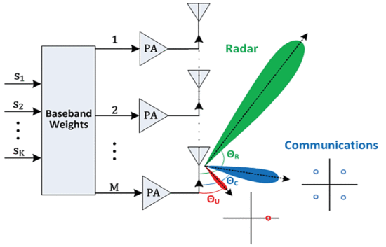
This work presents a uniform linear array (ULA) system, as shown in Fig. 1. This system can be adapted to various scenarios as described by the work in [7] [8]–[9]. The excitations of each element are derived from a fixed frequency carrier modified by a baseband-weighted vector and applied to subsequent per-element power amplifiers. The baseband-weighted vector is calculated in real-time using zero-forcing directional modulation (ZF) [3]. Since the ZF method is deterministic and presents a reasonable computational workload, it is suitable for a novel real-time implementation of this proposed system.
Block diagram for the simultaneous radar and spatially secure communications ULA transmitter.
Zero-Forcing Directional Modulation For Radar and Communications
The zero-forcing directional modulation problem begins with a description of the linear phased array, the directions of the intended signals with respect to the aperture, the phase of the intended signals, and the relative power allocated to each of the intended signals. The array has M elements uniformly spaced a distance d apart. The number of intended signals is given by the integer K, where ![]()
![]()
This work demonstrates the novelty of secure real-time multifunctional transmission in multiple real-time synthesis scenarios using the ZF method with the number of antenna elements M=16, the element spacing d= 0.5
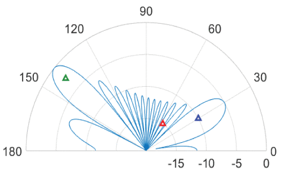
A multi-beam transmission pattern is presented. A main beam is sent to 140° that has a magnitude 5 times more powerful than the main beam sent to 30°. These beams represent the radar and communications directional transmissions, respectively. As shown in Fig. 2, a target is present within the radar beam, an intended receiver is present within the communications beam, and an unintended receiver (potential eavesdropper) is present within one of the sidelobes of the multi-beam pattern. A QPSK-modulated communications signal is sent to the intended receiver at 30°. A BPSK-modulated signal is simultaneously sent to the target of interest at 13 0 which is compressed to a radar pulse upon Barker code sequencing. The unintended receiver at 56.7° consequentially observes these transmissions.
Phased array spatial scene with a radar beam sent to detect a target (green) at 140°, a communications beam sent to an intended receiver (blue) at 30°, and an unintended receiver (red) located within one of the sidelobes at 56.7°.
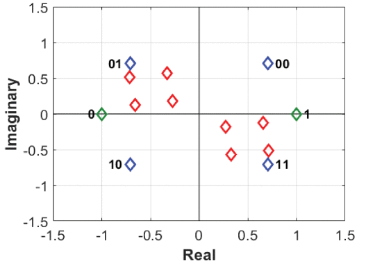
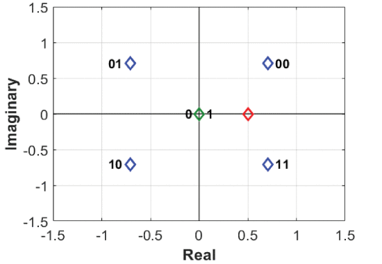
In the first transmission signal synthesis scenario, no ZF directional modulation is performed. Without any ZF directional modulation, the unintended receiver has the potential to recover the information sent to the intended receiver. Fig. 3 shows the superposition of constellation symbols for the unintended receiver when no measures are taken to prevent the signal sent to the intended receiver from being recovered in other directions. While the signal for the unintended receiver at 56.7° is affected significantly as shown in Fig. 3, with a potentially sophisticated demodulator, this unintended receiver still has some chance to recover the information.
Radar transmit mode constellation scene with a BPSK-modulated signal sent to 140° (green), and a QPSK-modulated signal sent to an intended receiver at 30° (blue) with an unintended receiver located at 56.7° (red).
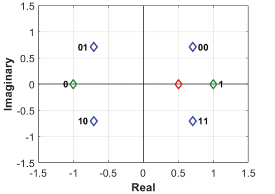
The next transmission signal synthesis scenarios are described by Figs. 4 and 5. The DM calculations of the baseband weights using the ZF method are modified to send intentional symbols to the unintended receiver during the transmit (Fig. 4) and receive (Fig. 5) modes of the radar. For baseband-weighted vector calculation, the relative powers are set to p1=1, p2=5, and the sum of the relative powers is set to
Radar transmit mode in which zero-forcing directional modulation is used to deliberately send the same symbols to the unintended direction of 56.7°.
Similarly, as shown in Fig. 5, the ZF method is applied to the radar’s receive mode where the magnitude of the radar transmission pulse is zero. The baseband weights are recalculated in real-time and still provide the desired constellation symbols to the intended receiver at 30° and the unintended receiver at 56.7°. This ensures spatially secure communications is maintained while the radar continues to transition from the transmit mode to the receive mode and vice-versa according to the structure of the synthesized radar pulse. While intentionally sending a constant symbol to a known unintended receiver direction is one method of ensuring that directional security is maintained, other ZF computations can be applied to accomplish the same goal.
Radar receive mode in which the ZF method is used to send the same symbols to the unintended receiver at 56.7°.
Barker Code Radar Signal Synthesis
To simultaneously synthesize the radar signal to have a transmit and receive mode as proposed in the previous section, N-length phase-coded Barker sequences are applied to compress the continuous BPSK signal into a radar pulse. The BPSK signal is compressed to a radar pulse with a length 2 Barker code, representing the Barker sequence of+1, -1. As customary with Barker sequencing, the radar pulse is divided into sub-pulses according to the sequence selected.
A. Range Considerations
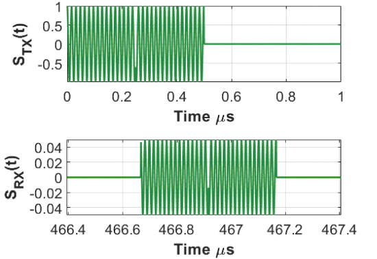
A relatively short length Barker code sequence was selected to minimize the radar signal pulse width so that a high bandwidth could be achieved, thus improving the range resolution of the radar signal. A sub-pulse width of 0.25 ![]()
![]()
Barker coded transmission for the radar signal at 140° at 3.6 GHz and its return signal from the moving target.
B. Ambiguity Function
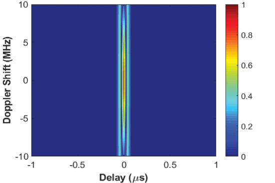
The ambiguity function of the simulated return signal is shown in Fig. 7. To justify acceptable monostatic range radar performance, it is desired that the waveform’s ambiguity function contains minimal ambiguity along the range axis, and this goal can be accomplished by using short pulses for the Barker code sequence. The ambiguity function optimization approaches of Eustice [10] may be applicable to optimize the Barker code waveform for different Range/Doppler resolution needs.
Ambiguity function for the moving target radar return signal centered at 3.6 GHz in the radar direction of
Conclusions
A phased array system that can provide simultaneous radar and spatially secure communications signals has been presented. This work combines directional security concepts from communications into a shared radar and communications framework using a single aperture. The computation of the appropriate phase shifts to apply to the excitation signals on each antenna element to maintain spatial security is significantly reduced. This provides a novel solution for a common phased array that requires suitable radar functionality as well as real-time spatially secure communications. Such a multi-functional system will allow spatial, temporal, and spectral resources to be more efficiently and securely used in the ever-crowded spectral environment.
ACKNOWLEDGEMENTS
This research has been funded by the National Science Foundation (Grant No. ECCS-1343316). The authors wish to acknowledge the assistance and support of Lawrence Cohen and William Crespo.

