Scheduled System Maintenance

On Tuesday, June 16, IEEE Xplore will undergo scheduled maintenance from 1:00-4:00 pm ET.
During this time, there may be intermittent impact on performance. We apologize for any inconvenience.

Fast Switched-Stub Impedance Tuner Reconfiguration for Frequency and Beam Agile Radar and Electronic Warfare Applications

Publisher: IEEE

Abstract: Tunable matching networks using switched stubs show promise for real-time impedance matching in high-power radar and jamming applications based on the emerging developmen... View more
Abstract:
Tunable matching networks using switched stubs show promise for real-time impedance matching in high-power radar and jamming applications based on the emerging developments of high-power switches. These self-tuning transmitter amplifiers will quickly maximize range upon changing operating frequency in a dynamically changing spectrum environment. In this paper, we present a fast tuning algorithm capable of maximizing the output power from a tuner with six switched stubs. The control of the tuner from a software-defined radio platform is demonstrated, and complete optimization for output power can be performed in under 35 μs following a change in operating frequency or antenna impedance. The algorithm is expected to be applicable to emerging high-power switches with similar reconfiguration times.
Date of Conference: 28-30 April 2020
Date Added to IEEE Xplore: 11 June 2020
ISBN Information:
ISSN Information:
Publisher: IEEE
Conference Location: Washington, DC, USA, USA

SECTION I.

Introduction

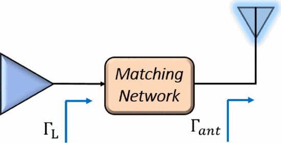
Future radar and electronic warfare (EW) transmitters will need to be frequency agile to quickly maximize range after changing frequencies in a dynamic, congested and/or contested spectral environment. High-power tuning technologies capable of fast reconfiguration, however, have heretofore not been available for use in radar and EW transmitters. The present state-of-the-art in high-power tuning technologies is a 90 W evanescent-mode cavity tuner using commercially available M3-L actuators, as presented by Semnani [1]. While this tuner presents novel high-power handling in the S-band, it reconfigures slowly due to the mechanical actuation of the discs atop the cavities. Recent results for demonstrating this impedance tuning from a software-defined radio platform with a host computer demonstrate search times of 2–10 seconds if initial information is not used and over 100 ms to perform a single tuning operation [2]. This merges the Semnani tuner with the software-defined radar controller platform, “SDRadar”, described by Kirk [3]. With the advent of high-power plasma-based switches [4][5], switched-stub tuners have become feasible for high-power impedance tuning with significantly reduced tuning times due to the electrical (rather than mechanical) actuation of the switches. In this paper, we demonstrate a complete search in less than 35 μs for a switched six-stub impedance tuner controlled by a software-defined radio. This algorithm allows tuning of changing antenna impedance to changing optimum-power load impedance for the preceding power amplifier. Fig. 1 shows a schematic of the matching network and illustrates its use in a high-power transmitter for radar or EW.

Fig. 1. - Real-time impedance matching network in radar and EW applications: The antenna reflection coefficient $\Gamma_{ant}$ is transformed to present the desired maximum-power load reflection coefficient $\Gamma_{L}$ to the transmitter power amplifier.
Fig. 1.

Real-time impedance matching network in radar and EW applications: The antenna reflection coefficient Γant is transformed to present the desired maximum-power load reflection coefficient ΓL to the transmitter power amplifier.

SECTION II.

Prototype Switched-Stub Tuner Design

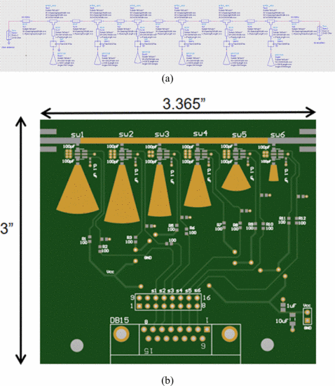
To demonstrate fast tuning, a prototype switched-stub tuner was designed with six tuning stubs, as shown in Fig. 2. Field-effect transistor (FET) switches were used in place of high-power switches on this board, which allowed for the development of the algorithm and fast control of the optimizations. A switch was placed between each radial tuning stub and the series feedline. Closing the switch exposes the stub, while opening the switch leaves the stub unattached from the feedline. The tuner was designed to fit within 4in.×3in.×3in. spatial constraints. The thickness of the printed circuit board is much smaller than the 3 i n. available from the remaining spatial dimension. The tuner was designed to obtain as close as possible to an octave of tuning bandwidth in the S-band from 2–4 GHz. Fig. 3 shows the coverage of the tuner at 2, 3, and 4 GHz. Because the tuner has six tuning stubs, and the switch between each stub and the main line can either be turned on or off, 64 states can be accessed through different combinations of switch actuations. The coverage is very broad at 2 GHz, reasonable at 3 GHz, and potentially useful but smaller at 4 GHz. Broader coverage (as seen at 2 GHz) is desirable for this application as it indicates greater tuner flexibility in matching for varied frequency and antenna impedance.

Fig. 2. - (a) Circuit schematic in keysight advanced design system and (b) Board layout for the prototype switched-stub tuner board: FET switches are used in place of high-power switches.
Fig. 2.

(a) Circuit schematic in keysight advanced design system and (b) Board layout for the prototype switched-stub tuner board: FET switches are used in place of high-power switches.

Fig. 3. - Measured tuner $s_{11}$ for all 64 tuner states at (a) 2 GHz, (b) 3 GHz, and (c) 4 GHz.
Fig. 3.

Measured tuner s11 for all 64 tuner states at (a) 2 GHz, (b) 3 GHz, and (c) 4 GHz.

SECTION III.

Reconfiguration Algorithm

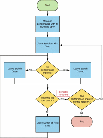
We designed a discrete search algorithm that can be used on this stub tuner with 26=64 possible tuner settings. Fig. 4 shows a flowchart of the search algorithm. A 6-bit binary word can be used to represent all switch states, beginning with the leftmost stub/switch combination from Fig. 2 (input side) and ending with the rightmost switch/stub combination. A 1 bit is used to represent a switch that is closed, and a 0 bit is used to represent a switch that is open. The algorithm is described as follows:

  1. Close the switch on the first stub (100000).

  2. Is the output power greater? If yes, leave this switch closed. If not, open the switch.

  3. Repeat for each stub in order from the amplifier side to the antenna side.

This entire search can be re-performed starting with the bit combination that is concluded as best in the first iteration and can be re-iterated as much as desired. Fig. 4 shows that the algorithm is re-iterated until no power increase is found during a search of the switch-state combinations one Hamming distance (one bit different) from the current best performing state.

Fig. 4. - Search algorithm for optimizing the switches on the stub tuner for maximum output power.
Fig. 4.

Search algorithm for optimizing the switches on the stub tuner for maximum output power.

SECTION IV.

Measurement Results

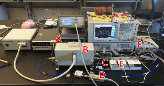
To test the algorithm, measurements were performed using a software-defined radio (SDR) controller and microcontroller synchronized with a host computer. The SDR, after calibration with a power meter, measures the amplifier output power, and the microcontroller performs the tuner movement. The host computer performs algorithmic decision-making during the development and experimentation phase. Eventually, all algorithmic decision-making and tuner control will also be placed in the SDR; however, adjustments to the SDR code during algorithmic development and testing are time-consuming due to the extended re-compile time required. The measurement setup is shown in Fig. 5. A traditional load-impedance tuner from Maury Microwave is used to emulate the changing antenna reflection coefficient Γant. A Microwave Technologies MWT-173 field-effect transistor (FET) is used as the transistor under test with VDS=4.5 V, VGS=1.4 V, and Pin=14 dBm, and the switched-stub matching network is placed between the FET output and the antenna-emulating Maury tuner.

Fig. 5. - Measurement setup: A - bias supplies, B - maury microwave tuner (emulating the antenna impedance variation due to mutual coupling), C - switched-stub tuner (representing the amplifier output matching network), D - microcontroller, E - amplifier, F - software-defined radio
Fig. 5.

Measurement setup: A - bias supplies, B - maury microwave tuner (emulating the antenna impedance variation due to mutual coupling), C - switched-stub tuner (representing the amplifier output matching network), D - microcontroller, E - amplifier, F - software-defined radio

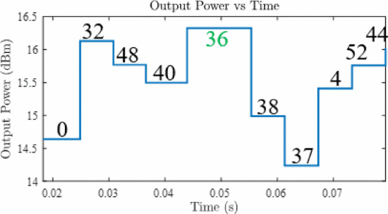
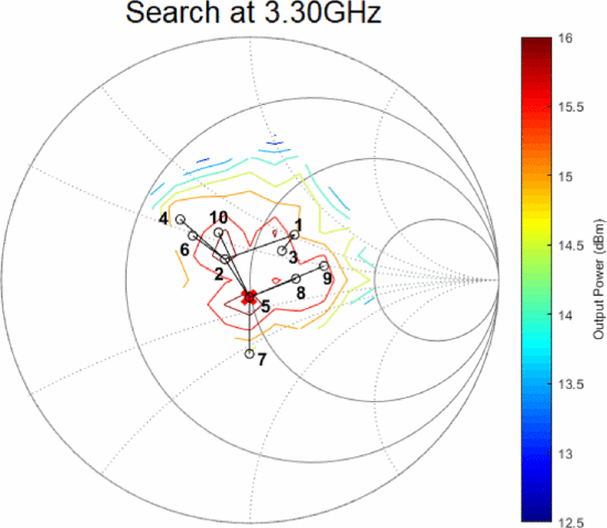
Graphical representations of the algorithm results for one search can be seen in Figs. 6 and 7, plotting the output power vs time as the search progresses and plotting the search path according to the tuner's S11 value at each state. This search was performed with an operating frequency of 3.3 GHz and Γant of 0. Both amplifier and antenna matching capabilities will be discussed in more detail later. In Fig. 6, the tuner states in the search are labeled on the plot in decimal format. This search converged to state 36 (100100) after 10 measurements with an output power of 16.33 dBm. The time for the entire search is approximately 60 ms, but the actual search times will be orders of magnitude shorter following implementation of the search solely on the SDR. The host computer and microcontroller, while requiring slightly larger search times, are much less cumbersome in the algorithm development and evaluation process.

Fig. 7 shows the 3.3 GHz search progress on the Smith Chart, mapping the bit combinations of Fig. 6 to ΓL values in the Smith Chart. In Fig. 7, the current measurement number is beside each ΓL search point on the Smith Chart. The black “o” symbols represent the search points, and the red “x” at measurement five corresponds to tuner state 36 (100100) where the search converged. The contours on the chart correspond to a load pull taken with the tuner at all 64 tuner states.

Fig. 6. - Output power vs time plot for one optimization search for both the MWT-173 power amplifier and Maury microwave tuner (simulated antenna).
Fig. 6.

Output power vs time plot for one optimization search for both the MWT-173 power amplifier and Maury microwave tuner (simulated antenna).

Fig. 7. - Progression of one optimization search on the Smith chart.
Fig. 7.

Progression of one optimization search on the Smith chart.

To test the algorithm for frequency agility, an experiment was performed where the search was performed at different frequencies between 2 GHz and 4 GHz. Upon switching frequencies, the stub tuner was reconfigured to maximize the output power of the amplifier. Table I shows the results of the optimization process for frequencies 2.0 GHz, 2.5 GHz, 3.0 GHz, 3.5 GHz, and 4 GHz with the binary states (0 = off, 1 = on for switches from stubs from the amplifier side to the antenna side of the matching network) and the related output power values.

For 2.0 GHz and 2.5 GHz, the state with all switches open and no stubs exposed to the series transmission line (000000) was selected as the best case. This is not surprising, as the introduction of a stub also results in loss to the forward transmission. As such, the optimization is more than simply selecting the state that gives the maximum-power ΓL, but the state that combines good power matching with minimal loss. In the 3 GHz and 3.5 GHz searches, different states are required to optimally match the device (010000 and 111000). The output power values vary from 17.77 dBm at 2.5 GHz to 13.49 dBm at 4 GHz. As could be expected, the maximum available power from the transistor decreases as frequency increases. The total time required for the searches ranges from 51.7 ms to 72.7 ms. This time decreases significantly when the search is run completely from the SDR, as is shown later in this paper.

Table I: Optimization of output power for the MWT-173 FET at 3.0 GHz by optimizing ΓL using the impedance tuner with Γant=0.
Table I:

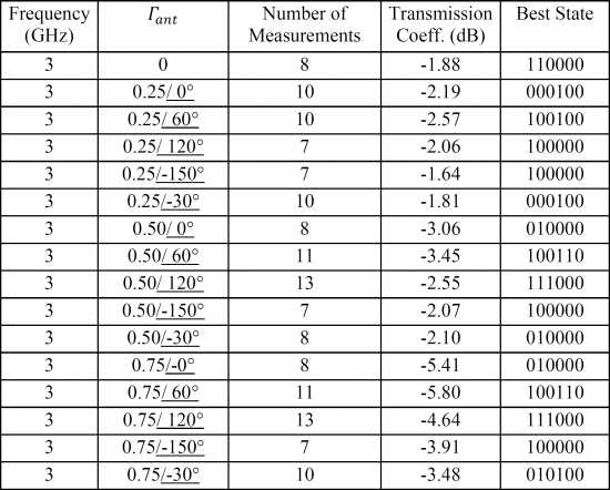
In addition to the frequency-agility test, the ability of the tuner to react to changes in the antenna impedance due to adjustment in the array pattern (“beam agility”) can be tested by tuning to optimize performance based on changes in Γant. Table II shows 3 GHz search results for different Γant values. A vector network analyzer (VNA) was used to measure the transmission coefficient for the stub tuner with the Maury Microwave tuner set to represent different values of Γant. Time is not considered in these measurements, as the VNA conducting the experiments is significantly slower than the setup with the SDR. Optimal switch combinations and ΓL values change significantly with changes in the antenna reflection coefficient Γant. Significant insertion loss is incurred in the tuner states required to avoid return loss for some of the Γant values.

Table II: Search results for optimizing output power at 3 GHz while varying ΓL
Table II:

The “Transmission Coeff” values in Table II are much lower than the “Max Power” values in Tables I and III due to the different measurement setup, as only the lower power VNA was used for transmitting rather than the SDR plus power amplifier. Certain Γant values lead to low transmission coefficients (e.g. −5.8 dB), and a future tuner would be designed with more attention dedicated to reducing loss. One option to consider would be shortening the length of the main RF feedline.

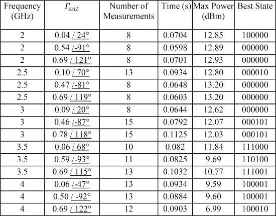
Finally, measurements were performed to emulate tuning in both frequency-agile and beam-agile scenarios, as shown in Table III. The search results change significantly with both frequency and Γant values in this experiment. The searches tend to converge with 10 to 20 measured points.

Table III: Search results for optimizing output power while varying ΓL and changing frequency within the 2–4 GHz octave.
Table III:

SECTION V.

SDR Implementation and Time Reduction

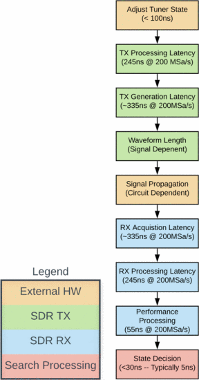
To streamline the time performance of the optimization, the algorithm was implemented completely on the SDR platform (eliminating the need for host computer and microcontroller, as well as the communication links between the different systems). For a single tuning operation, the host computer/SDR/microcontroller tuning time was measured at 5.231 ms. After implementation of the algorithm solely on the SDR, the tuning time for a single operation was reduced by three orders of magnitude to 1.88 μs, and an entire search was performed in 31.9 μs. This timing scenario allows for reconfiguration on the time order required to implement reconfigurable tuning into a real-time reconfigurable radar or EW system. Fig. 8 shows a timing diagram with a breakdown of the time required for each operation in a tuner reconfiguration algorithm step. This diagram shows that much of the time required for a tuning operation is needed to perform processing of the transmitted and received waveforms.

SECTION VI.

Conclusions

Fast reconfiguration of a switched-stub tuner has been demonstrated for frequency agility using a platform operated by a software-defined radio controller. Complete on-the-fly optimizations to maximize output power (and range) over changes in operating frequency and antenna reflection coefficient can be completed in less than 35 μs for the electrically actuated tuner, allowing dynamic performance on the order of time magnitude needed for spectrum and beam agility in radar and EW operations. The next step in this work is the implementation of this tuner architecture using high-power switches and demonstration of similar time performance and output power/range enhancement.

Fig. 8. - Timing diagram for searches performed in the SDR-only setup.
Fig. 8.

Timing diagram for searches performed in the SDR-only setup.

Top Organizations with Patents on Technologies Mentioned in This Article

References

1. A. Semnani, G.S. Shaffer, M.D. Sinanis and D. Peroulis, "High-Power Impedance Tuner Utilising Substrate-Integrated Evanescent-Mode Cavity Technology and External Linear Actuators", IET Microwaves Antennas & Propagation, vol. 13, no. 12, pp. 2067-2072, 2019.
2. A. Dockendorf, A. Egbert, E. Langley, C. Calabrese, J. Alcala-Medel, S. Rezayat, et al., "Fast Optimization Algorithm for Evanescent-Mode Cavity Tuner Optimization and Timing Reduction in Software-Defined Radar Implementation", IEEE Transactions on Aerospace and Electronic Systems, September 2019.
3. B. Kirk, K. Gallagher, J. Owen, R. Narayanan, A. Martone and K. Sherbondy, "Cognitive Software Defined Radar for Time-Varying RFI Avoidance", Proceedings of the 2018 IEEE Radar Conference, April 2018.
4. A. Semnani, S.O. Macheret and D. Peroulis, "A 2–30 W 5-Band Plasma-Based Switch", 2017 IEEE Wireless and Microwave Technology Conference, April 2017.
5. A. Semnani, S.O. Macheret and D. Peroulis, "A Quasi-Absorptive Microwave Resonant Plasma Switch for High-Power Applications", IEEE Transactions on Microwave Theory and Techniques, vol. 66, no. 8, pp. 3798-3806, August 2018.