Introduction
For radar transmission, larger bandwidth provides finer range resolution. However; in current shared spectrum environments, (i.e. the 3.45 to 3.7 GHz portion of the radar S-band allocation), sufficient contiguous bandwidth may not be available to achieve the necessary range resolution. Notched radar waveforms are a solution (e.g. [1][2]-[3]). Here we consider the notched pseudo-random optimized Frequency Modulated (PRO-FM) waveforms recently examined in [3], which also leverage the reiterative uniform weighted optimizations (RUWO) method of [2]. PA nonlinearities have undesirable effects on both adjacent-channel and notch power ratios [4], and the choice of load impedance affects both the spectral mask compliance [5] and notch depth. The impedance providing maximum PAE while meeting notch depth constraints is seen to vary significantly as the notch positions and widths change.
Load Impedance and Notch Depth
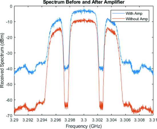
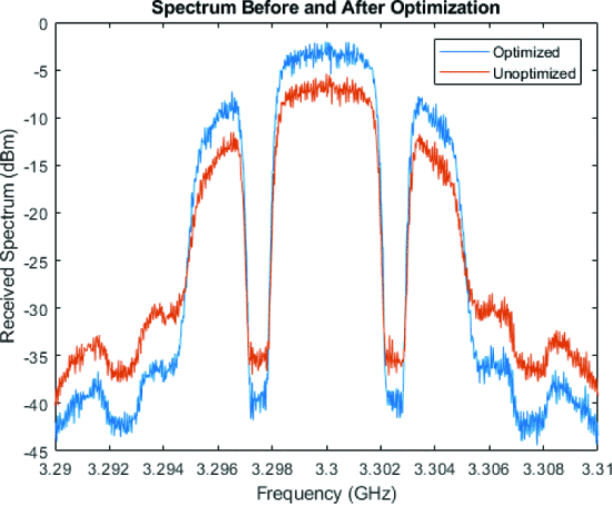
Introducing a notched waveform into a PA which is sufficient to drive it into a nonlinear operation results in spectral spreading into both the out-of-band and notched regions due to odd-order PA nonlinearities. Fig. 1 shows the spectra of PA input and output waveforms for a MWT-173 field-effect transistor (FET) at a center frequency of 3.3 GHz. While the in-band signal increases by approximately 8 dB, spreading into the notched and out-of-band regions increases their level by approximately 30 dB due to these PA nonlinearities. Fig. 2 shows amplifier output waveforms for two different load impedances, demonstrating that load impedance adjustment can recover the deep notches.
Amplifier output waveform for unoptimized (red) and optimized (blue) load-impedance values
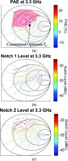
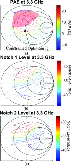
Fig. 3 shows a notched waveform from [3] with two notches centered at 3.3 GHz, which is, useful in a case where two interferers are present. In the following discussion, the left notch is denoted "Notch 1" and the right notch is denoted "Notch 2". The MWT-173 PAE and notch-level load-pull results for 3.3 GHz at VGS = -1.4 V, VDS = 4.5 V are shown in Fig. 4. These plots show that the deepest notch level and highest PAE are obtained at different Smith Chart locations. As such, selection of the amplifier load reflection coefficient ΓL can be performed by choosing the ΓL providing the highest PAE available while meeting a notch-level constraint. For example, if a notch depth ≥36 dBc (notch level ≤ -36 dBc) is required for both notches, the constrained maximum PAE is obtained at ΓL = 0.09 /122 °, resulting in PAE = 24.6%.
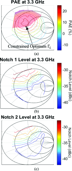
Fig. 5 shows a waveform template with two asymmetrically located notches, with Notch 2 depth greater than Notch 1 depth. Fig. 6 shows PAE and notch-level load-pull results, indicating that greater depth (lower level) is achievable for Notch 2 than for Notch 1. For Notch Level ≤ -36 dBc, Notch 1 dominates the constraint, resulting in a constrained optimum PAE = 23.7% at ΓL = 0.07/141°.
Fig. 7 shows the template for a waveform with two notches of different widths. Fig. 8 shows the load-pull results for PAE and depths of both notches. Over the Smith Chart region measured, the maximum depth achievable for Notch 1 is 43 dBc, while the maximum depth achievable for Notch 2 is 36 dBc. Notch 2 dominates the constraint, and for notch level ≤-34 dBc, the constrained optimum PAE = 22.5% at ΓL = 0.27/46°.
Conclusions
In transmitter nonlinear amplification of notched waveforms used for spectrum sharing, the load impedance significantly impacts the notch depth. The experimentally optimum load impedances for three different notched waveforms with the same PA vary significantly across the Smith Chart. These variations show the need for real-time reconfiguration of amplifier load impedance to maintain range as the spectral notches are shifted due to changing interference.
Measured 3.3 GHz load-pull for (a) PAE, with the shaded region of insufficient notch depth and constrained optimum ΓL; (b) Notch 1 Depth; and (c) Notch 2 Depth for the Fig. 3 waveform
Measured 3.3 GHz load-pull for (a) PAE, with the shaded region of insufficient notch depth and constrained optimum ΓL; (b) Notch 1 Depth; and (c) Notch 2 Depth for the waveform depicted in Fig. 5.
ACKNOWLEDGEMENT
This research was funded by the Army Research Laboratory (Grant No. W911NF-16-2-0054). The views and opinions expressed do not necessarily represent the opinions of the U.S. Government.

![Fig. 3. -
Notched waveform from [3] with symmetric notches of the same width](2020-Notched-Waveforms_files/docke3-p3-docke-small.gif)
![Fig. 5. -
Notched waveform from [3] with asymmetrically centered notches of the same width.](2020-Notched-Waveforms_files/docke5-p3-docke-small.gif)
![Fig. 7. -
Notched waveform from [3] with asymmetric notches of different widths.](2020-Notched-Waveforms_files/docke7-p3-docke-small.gif)
