Introduction
The re-allocation of radar S-band spectrum for sharing with wireless communications is only the most recent example of an ongoing trend that is driving research on radar spectrum sharing [1]–[2][3][4][5][6][7]. One method of sharing is for the radar to transmit in a contiguous band of frequencies that changes based on the radio frequency interference (RFI) gleaned from the environment. In such scenarios, a tunable matching network can be placed after the transmitter power-amplifier device and tuned in real-time to operate between the RFI frequencies [8]. Real-time tuning of the amplifier is useful because the output power, the power-added efficiency (PAE), and the adjacent-channel power ratio (ACPR) of an amplifier all depend on the load impedance presented to the amplifier [9], which is also affected by changing antenna impedance due to mutual coupling in arrays [10]. Real-time circuit tuning under control of a cognitive radio platform can therefore improve output power in frequency/beam agility scenarios. Kirk [11] likewise demonstrates the use of a software-defined radio (SDR) platform to maximize bandwidth, signal-to-interference-plus-noise ratio (SINR), and target-to-clutter ratio for spectrum sharing by sensing the spectrum, and then choosing the band for transmission.
In some sharing scenarios, rather than change the contiguous band of operation, spectral notches [12]–[13][14][15] can be placed within the transmitted radar bandwidth at the particular sub-bands occupied by RFI. A recent approach has relied upon the inherent maneuver freedom of random FM waveforms [16] to incorporate notches. Specifically, Jakabosky [17] demonstrates Tukey windowing to taper the range sidelobes otherwise induced by sharp notch edges, and Mohr [18] uses a spectral frequency-template error (FTE) metric for optimization of notched waveforms. Ravenscroft [19] provides an holistic perspective on the use of notched random FM waveforms for radar detection in an environment with stationary and dynamic RFI, integrating this approach into a cognitive radio platform using a perception-action cycle for spectrum sensing, decision making, and adaptation. Valette [20] subsequently discusses the interaction of notched waveforms with power amplifier nonlinearities.
In [21] Semnani demonstrates a 90 W evanescent-mode (EVA) cavity impedance tuner that provides the capability to reconfigure within hundreds of milliseconds by adjusting the positions of discs atop its two cavities, with loss of only ∼0.75 dB across most of the Smith Chart. This tuner is likewise shown by Alcala-Medel [8] to be frequency-agile over the S-band radar allocation using fast tuning algorithms developed by Dockendorf [22]. Here we demonstrate the use of this cavity tuner to perform impedance tuning for spectrally notched waveforms, providing the capability to optimize the power amplifier nonlinearities to obtain desirable notch depth and out-of-band spectral performance while maximizing the radar range.
Measurement Results: Impedance Tuning Implications on the Decision to Notch or Avoid
With the availability of notched waveforms (e.g. [12]–[13][14][15][16][17][18][19]), a cognitive radar may either notch around RFI frequencies or avoid the interference by selecting a smaller contiguous bandwidth. The impedance tuning considerations contribute to an engineering trade-off that must be negotiated between these two operating conditions. If a “notch” decision is made, the matching circuit can be tuned to maximize the power under the stringent consideration of meeting the sharp notch roll-off. If nonlinearities in the power amplifier cause intermodulation that fills the notch, then the load impedance must be tuned to focus on linearizing the amplifier device rather than improving the output power. As such, the greater bandwidth available from the notched waveform, and accompanying improvement in range resolution, might come at a sacrifice of output power and a related undesirable decrease in radar range.
In performing experiments to investigate the trade-off between range and range resolution for the “notch” and “avoid” cases, the Baylor research team performed measurements on two versions of notched random FM from the University of Kansas, which inherently possess constant amplitude. Because their generation involves spectral shaping optimization, both to ensure good spectral roll-off in the out-of-band region and to initiate spectral notches, the deployment-ready version of each waveform exists in a discretized form that must be appropriately implemented as a continuous waveform in hardware. For example, [24] discusses the process required to realize spectrally notched waveforms on the modest fidelity available on an SDR platform.
For high-fidelity implementations such as can be achieved with an arbitrary waveform generator (AWG) it is necessary to up-sample the waveform to the DAC rate of the AWG. However, if these waveforms are sinc-interpolated when upsampling, which would seem to be the obvious approach, significant amplitude modulation (AM) in the time-domain can arise. Consequently, AM to phase modulation (AM-PM) nonlinearities in the power amplifier can cause spectral spreading, thus resulting in significant degradation of notch depth [23].
On the other hand, constant amplitude can be preserved by performing interpolation solely in the phase domain. As such, AM-PM conversion does not become an issue, and impedance tuning can be used to maximize output power rather than being traded to improve linearity and thereby maintain notch depth.
We shall herein show two examples of using real-time impedance tuning with notched waveforms for radar applications. The trade-off between range and range resolution is examined for sinc-interpolated (non-constant modulus) and phase-interpolated (constant-modulus) notched waveforms. The benefit of using phase-interpolated waveforms is confirmed through these experiments to benefit both range and range resolution.
A. Sinc-Interpolated Notched Waveforms
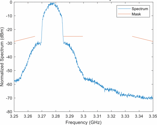
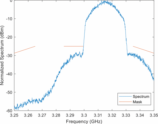
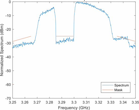
A simplified spectrum sharing scenario is constructed involving an overall bandwidth of 60 MHz at a center frequency of 3.3 GHz (3.27–3.33 GHz). RFI having 15 MHz bandwidth is assumed to reside within the sub-band between 3.285 and 3.3 GHz (i.e. 15 MHz from the lower end of the band and 30 MHz from the upper end). Consequently, the cognitive radar controller has three options to operate without interference: “avoid low”, “avoid high”, or “notch”. A comparison of these three options based on best performance obtainable through impedance tuning is examined.
Figure 1 shows the “avoid left” possibility, where a contiguous-band random FM waveform is synthesized to be lower than the 15 MHz RFI (indicated by the center red line). Likewise Fig. 2 shows the “avoid high” possibility where a contiguous-band random FM waveform is synthesized higher than the RFI. This case achieves a wider bandwidth than Fig. 1 because there is more available spectrum as specified by the mask. Finally, Fig. 3 shows a notched random FM waveform that has been sinc-interpolated, thus realizing a notch depth of about 30 dB. Clearly, a notched waveform provides more total bandwidth than the avoidance-based waveforms, thereby providing better range resolution, because it can make use of the available spectrum on both sides of the RFI.
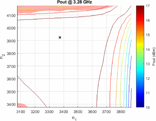
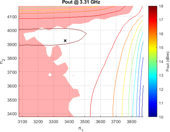
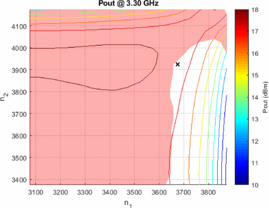
For each of these waveforms and their corresponding spectral mask, a full load-pull measurement was performed using the Purdue University Generation 2 EVA cavity tuner over the combinations of the two cavity position numbers (
Output power load-pull measurement results in tuner cavity position number combinations (
Figure 6 shows that the sinc-interpolated implementation of the notched, random FM waveform causes very little of the (
Output power load-pull measurement results in tuner cavity position number combinations (
B. Phase-Interpolated Notched Waveforms
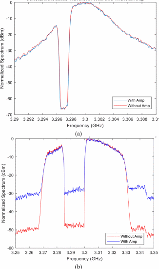
In contrast to the sinc-interpolated implementation considered above, now consider a phase-interpolated implementation that preserves constant amplitude (per [19]). Consequently, the possibility of AM-PM conversion from amplifier nonlinearities is eliminated. Figure 7(a) shows the normalized spectrum for a phase-interpolated random FM waveform, with and without an amplifier terminated in an impedance resulting in significant nonlinearities. For comparison, Fig. 7(b) shows the sinc-interpolated waveform for the same conditions.
The former case, where the contant amplitude is preserved, realizes negligible difference with or without the amplifier in Fig. 7(a). This result is expected because, by maintaining the FM structure, the waveform is well-suited to a high power amp. Alternatively, the sinc-interpolated case in Fig. 7(b) shows roughly 20 dB of degradation in notch depth due to the distortion that is ultimately caused by AM imposed on the signal that translates into AM-PM nonlinearity in the amplifier.
Simply put, the even seemingly innocuous details of the implementation become quite important when high power and high fidelity are both required.
(a) Phase-interpolated random FM waveform with and without power amplifier and (b) Sinc-interpolated random FM waveform with and without power amplifier. Both waveforms were measured at the same tuner (
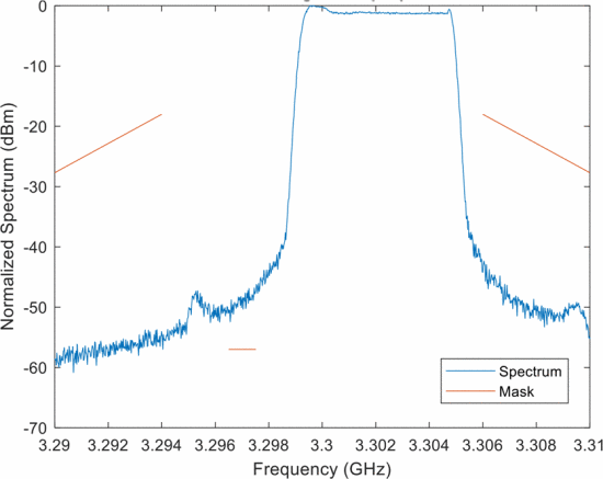
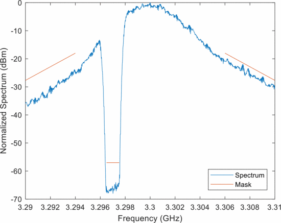
Figures 8 and 9 compare use of an “avoid high” LFM chirp and a notched, random FM waveform (phase-interpolated), respectively, to determine the best range and range resolution that can be obtained given a set of spectral constraints that dictate the out-of-band roll-off and avoidance of a 1 MHz RFI source (with acceptable transmit power of −57 dBm). Here the former case has a 6 MHz bandwidth to (mostly) achieve the desired spectral constraints, while the latter employs all of the available 20 MHz, aside from the 1 MHz notch. Further, the LFM does not meet the RFI avoidance criterion, while the notched waveform achieved the required notch depth with room to spare.
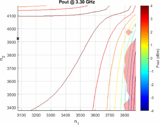
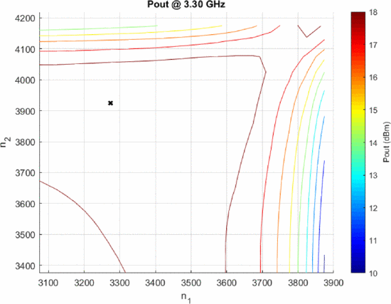
Figures 10 and 11 show the output power load-pull contours for the waveforms in Figs. 8 and 9, respectively. The power of the “avoid” chirp must be reduced to meet the depth enforcement aspect of the mask for the 1 MHz RFI. The loadpull result for this waveform (Fig. 10) shows a maximum output power of approximately 4 dBm. However, Fig. 11 shows a maximum output power of approximately 18 dBm for the notched waveform (phase-interpolated), with the entire (
Table II depicts a comparison of the search results between the “notch” and “avoid” cases for the scenario above. A range of 16.91 km is available with the notched, random FM waveform, while only 7.91 km of range is available with the “avoid” chirp waveform at the optimum output power load impedance. Additionally, the notched waveform provides finer range resolution due to the use of all available bandwidth.
Output power load-pull measurement results tuner cavity position number combinations (
Output power load-pull measurement results tuner cavity position number combinations (
Conclusions
An investigation has been presented on the impact of impedance tuning upon the decision of whether to use a notched waveform or contiguous-band waveform when a cognitive radar is contending with in-band RFI. The implementation of (discretely) optimized waveforms on an AWG also plays an important role, with standard sinc-interpolation leading to rather significant degradation due to AM-PM amplifier nonlinearities that necessitate power back-off to compensate. In contrast, phase-interpolation preserves the FM structure of the waveform, thereby avoiding these AM-PM effects altogether. Consequently, both range and range resolution can be optimized through impedance tuning without fear of inducing undesired spreading into the notch. These results are critical in integrating amplifier limitations into cognitive-radar decision making where notching or avoidance of RFI is required.
ACKNOWLEDGMENT
This work has been funded by the Army Research Laboratory (Grant No. W911NF-16-2-0054 and W911NF-15-2-0063). The views and opinions expressed do not necessarily represent the opinions of the U.S. Government. The authors are grateful to John Clark of the Army Research Laboratory for assistance in development of this paper.


