Introduction
Spectrum sharing has never been more important for radar systems. A recent ruling known as “America's Mid-Band Initiative” in the United States has re-allocated 100 MHz of the former S-band radar allocation to fifth-generation (5G) wireless as the new primary user [1]. Radar transmitters must be able to adaptively and reconfigureably share the spectrum previously allocated solely for their use. Frequency-agile radar transmitters can be enabled by placing reconfigurable impedance tuners between the power amplifier and the antenna to provide adaptive matching, as shown in Fig. 1. The matching is adjusted upon changes in operating frequency and scan angle to re-match the amplifier to the antenna to maximize detection range and power efficiency. High-power, high-speed tuners are needed to enable frequency-agile radars.
Previous impedance tuners have typically shown either high-power or high-speed capabilities, but not both, evident in [2]–[3][4], using technologies such as MEMS switches, varactors, and ferroelectric materials. Additionally, computer automated reconfiguration of impedance tuners has been demonstrated in [5]–[6][7]. Semnani [8] has developed an evanescent mode cavity tuner capable of handling 90 W; however, it is limited in speed by the mechanical tuning process, which is performed by M3-L linear actuators.
Simple block diagram representing use scenario for reconfigurable matching network between power amplifier and antenna array element. Reprinted from [11].
With this 90 W tuner, Dockendorf demonstrates searches performed in 2–10 seconds and near 100 ms without and with prior information available [9], respectively, making use of a software-defined radar spectrum sharing application [10]. Faster tuning is needed for real-time radar adaptation, prompting the recent examinations of electrical high-power tuning capabilities. A low power prototype switched-stub impedance tuner is demonstrated by Calabrese, capable of full optimization searches in under 25 µs [11] and is the design base for the high-power tuner in the present paper. Switches using fiber-coupled laser excitation of semiconductor plasma in custom chiplets are demonstrated by Fisher [12]. While the chiplets have been shown to be able to handle 35 W [13], high power testing of the tuner has not yet been performed, although a test plan is currently in development. The present paper demonstrates the use of high-power semiconductor plasma switches in creating a fast impedance tuner using the 35 W switches capable of optimizing output power in approximately 260 µs, an improvement of over three orders of magnitude from presently available high-power tuners [9].
Prototype Switched-Stub Tuner Design and Measurements
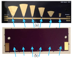
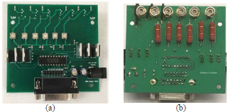
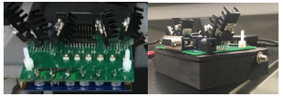
The tunable matching network design hinges upon the ability of the laser diodes to illuminate the silicon chiplets, with the help of gradient index (GRIN) rod and spherical lenses, creating semiconductor plasma and effectively closing the switches. A two-board design is used for implementation of control circuitry with the laser diodes. The RF board, shown in Fig. 2, utilizes the same radial matching stub topology of the Calabrese low-power prototype [11]. The radial stubs were chosen for their bandwidth performance and were empirically adjusted to achieve favorable RF performance. Each of the six switches is a custom silicon chiplet which is placed over a via, bridging the gap between the RF feedline and a stub, exposed whenever the switch is closed. The lenses are placed inside the vias to focus the laser light and provide a higher power density across the gap of the chiplet, decreasing the resistance and total loss of each semiconductor plasma switch. The other board, the control board, shown in Fig. 3, includes six commercially available 500 mW, 808 nm laser diodes with circuitry allowing control by a microcontroller or software-defined radio (SDR). The boards are attached and spaced apart using nylon screws and spacers, allowing the laser diodes to illuminate through the vias on the RF board and excite the silicon, and are ultimately placed in a PCTG housing, shown in Fig. 4, to contain any stray near-infrared (NIR) beams.
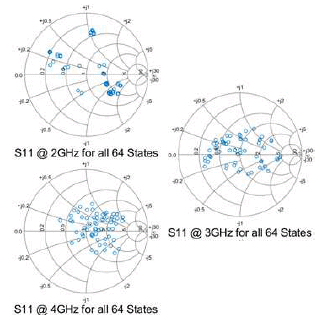
With six matching stubs, the tuner can achieve 26 = 64 unique matching states. Tuner characterization was performed using a vector network analyzer. Fig. 5 shows
(a) Bottom of rf board. Arrows point to 3.075 mm x 0.5 mm silicon chiplets (b) top of rf board. Arrows point to 1 mm diameter vias which allow illumination of silicon chiplets. The lenses sit in these vias.
(a) Top of control board (b) bottom of control board with laser diodes attached at the top
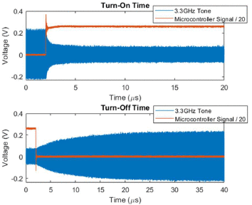
An RF oscilloscope was used to measure the time taken for the RF signal to respond to the switches opening and closing. A microcontroller was used to turn the laser diodes on and off and was also used to trigger the oscilloscope measurements. Fig. 6 show off/open timing measurements, run by a microcontroller and measured by an oscilloscope. The lossiest tuner state was used for timing measurements, so the RF tone, shown in blue on the figures, decreases in magnitude when the silicon chiplet switches are closed and increases when they open. Using the metric of 10-90% of the voltage to determine the switching time, the on-time was calculated to be near 2 µs, and the off-time 20 µs, Impedance optimization searches, discussed later, often do not need to wait the full 20 µs for accurate convergence to the optimal tuner state for a given frequency and “antenna” reflection coefficient pair.
Impedance Optimization Search Results
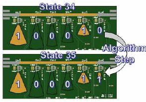
Applying the discrete search algorithm presented by Calabrese for the low-power switched-stub tuner [11] in a field-programmable gate array (FPGA), impedance optimization searches were performed with the tuner. The six switched stubs are represented by a binary 1 or 0, and the 64 tuner states are cycled through one bit at a time. If output power improves, the switch that was most recently toggled on or off keeps its current form, which provided the improvement, open or closed. These steps continue until an entire pass through all stubs provides no further performance improvement. Fig. 7 shows an example of an algorithm step, using the tuning stubs as a visual. The tuner begins at state 34 here and leaves the fifth switch closed due to a performance improvement. The next step is to retune to state 35 by closing the sixth switch. The output power would be remeasured. If an improvement is seen, the sixth switch would remain closed; otherwise, it would be opened. The first switch would then be revisited, and passes through toggling all switches continued until a complete pass results in no further power improvements.
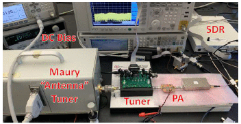
Fig. 8 shows the test setup. The software-defined radio (SDR) generates the 3 dBm input signal and measures output power. A Skyworks 65017-70LF InGaP amplifier was used as the amplifier device, and the plasma tuner was placed at the output of the device. A commercial impedance tuner from Maury Microwave was used to emulate the changing antenna impedance that could result from varying array scan angle.
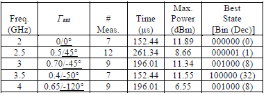
Table 1 shows five
examples of optimization searches using the laser diode-silicon chiplet
tuner. For example, the search on the center row was performed at 3 GHz
and an “antenna” reflection coefficient
Timing measurements for switch close (on) time and open (off) time of laser diode/silicon chiplet switches
The loss of the tuner is significantly dependent on the tuning state selected. A loss of near 1 dB can be obtained for some of the zero- and one-stub states. Typically, closing more switches (exposing more stubs) raises the loss, explaining the limited states appearing in the results of Table 1. At times, although a certain state can provide a good match, the additional loss is too high for that state to be chosen. As such, some of the end power values are low because a tuner state providing both a good match and low loss does not exist. We are currently investigating a single packaged switch including the chiplets and laser that would eliminate light divergence and slight alignment inconsistencies, reducing the loss significantly. An intermediate solution that could provide further loss improvement of states with more exposed stubs would include a high-precision housing for the diodes, chiplets, and lenses.
Conclusions
Design and fast optimization of a 2–4 GHz S-band impedance tuner using 35-W semiconductor plasma switches has been presented. The tuner can provide complete optimization of impedance in approximately 260 µs from a software-defined radio platform, helping a radar system maintain optimal output power and detection range. In addition to enabling spectrum-sharing radar in the S-band, the design will also be useful in other high-power transmitter applications, including satellite communications and cellular phone base stations.


![Fig. 1. - Simple block diagram representing use scenario for reconfigurable matching network between power amplifier and antenna array element. Reprinted from [11].](2021-PLASMA_files/9574975-fig-1-source-small.gif)
