Introduction
An important application of cognitive radar is the ability to share spectrum in real time. Recent reallocations of the radar S-band in the United States have increased demand for radars that can quickly adapt in operating frequency while maintaining transmission range [1], [2]. A paradigm shift is underway from traditional static frequency allocations to dynamic spectrum access for radar [3]. Upon reconfiguring for transmission at different frequencies, the transmitter power-amplifier output power should be optimized to maximize the radar detection range. This can be performed by reconfigurably loading the amplifier with its maximum-power load impedance over variations in frequency and antenna impedance [4].
While a broadband fixed output matching network can be used for wideband matching, it suffers from lower gain than is available in a tunable output matching network, as detailed in [5]. An adaptive amplifier module introduced by Kingsley and Guerci is programmable for maximum-power, linearity, or efficiency load impedances of the transmitter power amplifier, with 100 W power handling [6]. Real-time impedance tuning for allowing for fast reconfiguration of a switched-stub tuner was demonstrated by Calabrese [7], [8] using a platform operated by a software-defined radio controller. The “SDRadar” platform is demonstrated by Kirk as a real-time spectrum-sharing radar that reacts to its ambient spectral environment [3]. The present paper presents the novel integration of the Calabrese tuner [7] with the SDRadar platform [3], providing integrated spectrum-sharing control and circuitry for radar transmitters to maintain and optimize performance synchronized with radar pulses in real time.
Cognitive Radar System
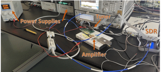
The cognitive radar “SDRadar” system of Kirk [3] and the real-time impedance tuner of Calabrese using a switched-stub design [7] are used to demonstrate real-time tuner optimization in a cognitive radar. The SDRadar implements a perception action cycle for spectrum sharing whereby the RF spectrum is sensed, other RF signals are identified, and the radar frequency band is adjusted to avoid interference [3]. The switched-stub tunable matching network uses a topology that is expected to be capable of high power handling when using high-power semiconductor plasma switches [7]. This paper combines Kirk and Calabrese's systems for a highly adaptive real-time impedance tuned radar. The hardware setup for this system is shown in Fig. 1.
A. Software-Defined Radar System
This work uses a modified version of Kirk's SDRadar [3], [9], which is able to intelligently detect and adapt to interference for improved radar detection, along with a Skyworks SKY65017-70LF amplifier with 3 dBm input power. As demonstrated by Egbert [10], this system will monitor the amount of interference in its current 100 MHz band, and it will switch to a different 100 MHz band if the interference occupies more than a set percentage of the band. Although the SDRadar has the further capability to adapt to interference within a 100 MHz band, we have disallowed this capability for these experiments. This restriction simplifies the tuner integration of Section III. Future work is planned to lift this restriction while maintaining the same level of integration.
B. Real-Time Impedance Tuner
The Calabrese impedance tuner shows a real-time impedance tuner that is controlled with fast electrical switches allowing the tuner to reconfigure in less than 35 µs, when measurements are performed as quickly as possible without pulsing on and off for radar operation [7]. The tuner uses open-circuit radial stubs connected along the main transmission line, with Analog Devices' HMC550A switches to introduce different combinations of the six stubs on the transmission line. The Calabrese algorithm used to control this tuner design proceeds by toggling the state of each switch one at a time [7]. The algorithm is shown to determine the optimum in as few as one to three iterations. The 64-state tuner is able to reach a broad range of the Smith Chart, thus enabling a match for multiple, unknown combinations of frequency and antenna impedance that may be encountered.
Tuner Integration With Sdradar
Because of the tuner's fast reconfiguration time, the described SDRadar system and real-time impedance tuner were integrated synchronously, allowing for rapid reconfiguration times within the transmit and receive time structure of the radar. When the mechanical tuner of Semnani [11] was previously implemented in the SDRadar framework [10], the mechanical nature of the tuner caused impedance adjustments to require much longer intervals (30–100 ms) than the SDRadar's pulse repetition interval (PRI) of 409.6 µs. Integration of the Semnani tuner into the SDRadar was asynchronous, with adjustments made over the course of separate pulses [10]. This approach leaves the radar open to possible mid-pulse distortions, as analyzed by Egbert [12]. While such distortions can be mitigated with the techniques of Egbert [12] and Kirk [9], it is generally preferable to prevent distortion when possible.
For synchronous operation, the tuner algorithm implementation was adjusted to ensure impedance adjustments were made outside of the transmission window of the SDRadar (during the radar's “listen” interval). Previous demonstrations of the tuner used short test waveforms and proceeded to the next impedance in the search as quickly as possible. However, when integrating the tuner into the SDRadar system, the rate of optimization is driven by the PRI of the radar. For this demonstration, the SDRadar operates with a PRI of 409.6 µs, with the rate of impedance optimization throttled to one impedance evaluation per pulse. Additionally, the radar transmits across its entire 100 MHz band, rather than adapting to interference within its band. By transmitting over the full band, the same waveform is transmitted at each pulse until a change in frequency occurs. Thus, the search can quickly determine the optimal state and hold the optimal tuner state for improved output power until the system is presented with too much in-band interference, causing the system to hop to a different frequency band. Measurements were performed to show the improvements in output power and the reconfiguration time needed for the system to find the optimum after a change in frequency. To trigger changes in the SDRadar's operating band, interference was presented to the SDRadar system in loopback from the second SDR transmit channel, with full-band interference being presented at random time intervals no greater than 100ms.
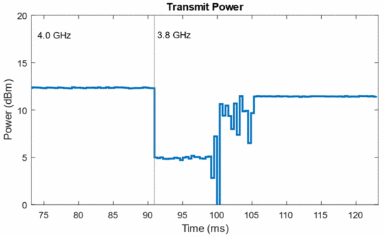
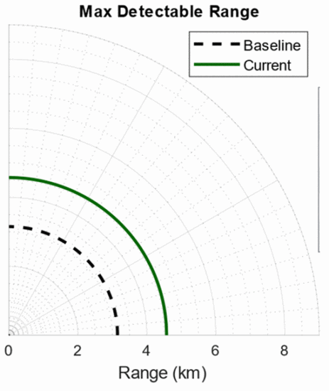
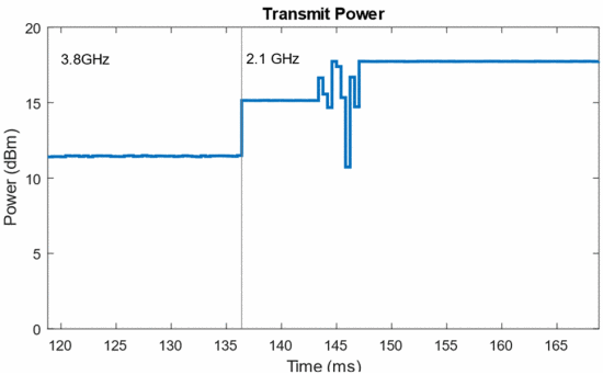
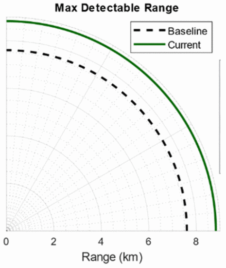
With the setup shown in Fig. 1, the change in output power over time and the improvement in maximum detectable range over the baseline were examined for multiple searches. Table 1 shows the results of fast tuning at four different frequencies used in the band-hopping caused by interference. A video can be constructed and played to show the real-time maximum detectable range compared to the “baseline” range before tuning, as well as the transmit power over time. Snapshots of the output power versus time and calculated maximum detectable range are shown for Search 2 (Figs. 2 and 3) and Search 3 (Figs. 4 and 5).
In Search 2 (Figs. 2 and 3), the system was presented with enough interference to cause a frequency hop from 4 GHz to 3.8 GHz. The power-versus-time results of Fig. 2 show a delay between the change in frequency and the start of the search. This is due to communication latency between the host side code and the software-defined radio. This latency can be reduced by migrating more of the band-hopping implementation to the FPGA from the host CPU. After the delay, the optimum is found in 6.55 ms and provides the system with a large increase in output power. Using typical radar parameters, a range improvement from about 3.1 km to 4.5 km is achieved, as shown on the screen-capture of the range indicator (Fig. 3).
Fig. 2 shows that the optimal output power after the search is less than the optimum output power before the change in frequency. This is partially due to frequency-dependent amplifier input power from the SDRadar over the full 2–4 GHz band, which is only adjustable in 0.5 dB increments. The tuner also has a variable frequency response, leading to some frequencies having higher performance at their optimum load impedances than other frequencies.
Search 3 is prompted by interference that causes a band hop from 3.8 GHz to 2.1 GHz. Fig. 4 shows that the reconfiguration of the system resulted in an increase in output power and range in 3.69 ms. The optimum was found with fewer measurements in this search, resulting in this small reconfiguration time. Searches 1 and 4 were able to complete in even fewer measurements than Searches 2 and 3, requiring only 2.87 ms. Table 1 summarizes the results from the full test, including each frequency change, search time, and performance statistics.
For all four searches, the tuner was able to improve the performance of the system above the unoptimized baseline power and radar range. The advantage of using a real-time impedance tuner is clearly shown, as the system was able to obtain consistent range improvement (up to 46 percent) when re-tuning after changing operating frequency. This synchronous approach to optimization enables the SDRadar system to maximize output power for the current operating conditions of the system multiple orders of magnitude faster than has been demonstrated with previously integrated tuners [10].
Conclusions
Integration of real-time impedance reconfiguration into a cognitive spectrum-sharing radar framework have been demonstrated. By using a real-time impedance tuner in the SDRadar system, the system increased output power values calculated to result in up to 46 percent improvement in radar range, whereas reconfiguration times are multiple orders of magnitude faster than mechanically actuated tuners had previously achieved in the SDRadar framework [10]. The actual use of electrically actuated tuners similar to the one demonstrated in these experiments is beginning to appear feasible based on recent developments in switched-stub tuners with semiconductor plasma switches [8]. High power semiconductor plasma tuners are being developed that would be able to handle the power needed for implementation in a radar while maintaining fast reconfiguration times. The implementation of a real-time impedance tuner would allow the radar to operate at its optimum and quickly adjust to changes observed in the environment.
ACKNOWLEDGMENTS
This work relates to Department of Navy award (Award No. NOOOI4-19-1-2549) issued by the Office of Naval Re-search. The United States Government has a royalty-free license throughout the world in all copyrightable material contained herein. This work has also been partially funded by the Army Research Office (Grant No. W911NF-20-2-0270) and the Army Research Laboratory (Grant No. W911NF-16-2-0054). The views and opinions expressed do not necessarily represent the opinions of the U.S. Government.

